UNIVERSITY OF FLORIDA / EML 2322L
Design & manufacturing laboratory.
Turning production drawings into machined parts and a working pneumatic air engine.
01 / THE WORKING ASSEMBLY
From compressed air to rotation.
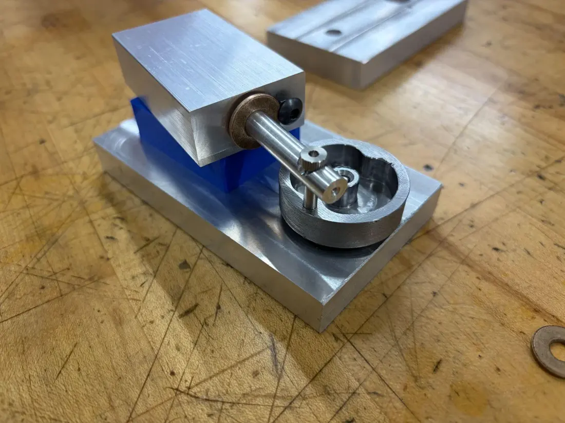
Our team manufactured and assembled a pneumatic engine that converts compressed air into continuous rotational motion through a piston-driven crank mechanism.
I made the piston and piston block and contributed to the engine’s assembly and testing. My drawings define the dimensions and features of both components.
02 / MY DRAWING & MACHINING WORK
Defining the piston.
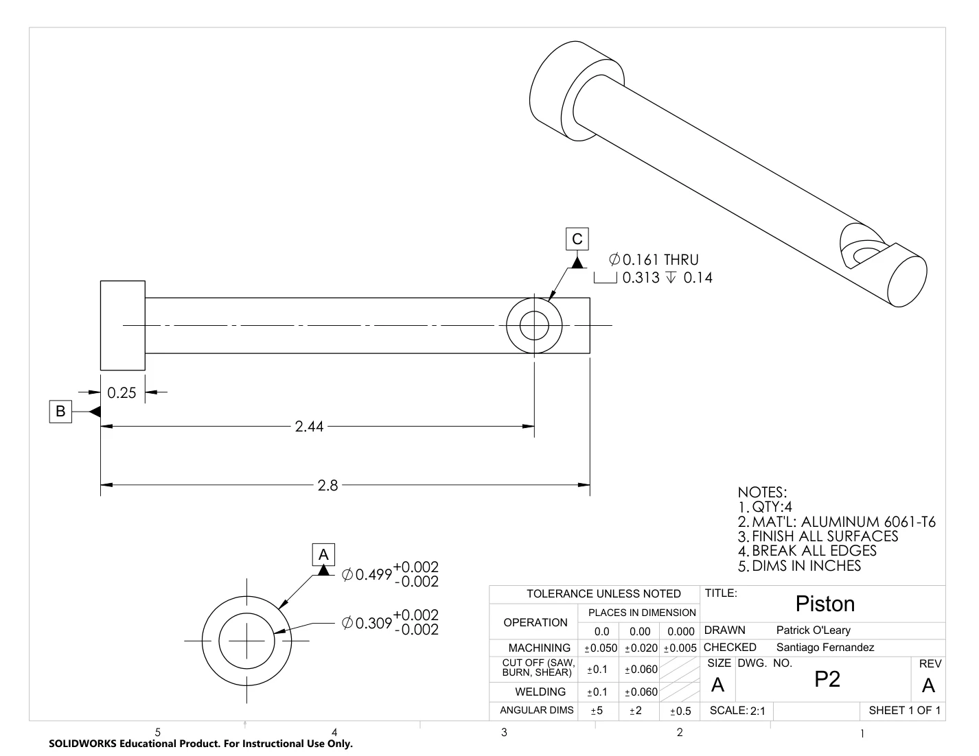
I produced the piston drawing in SolidWorks and machined the component. The drawing specifies the stepped diameters, overall length, through-hole, counterbore, and dimensional tolerances.
This connects the drawing to the manufacturing process: selecting operations, measuring features, and checking whether the component meets its dimensional requirements.
03 / MY PRODUCTION DRAWINGS
Piston & piston block.
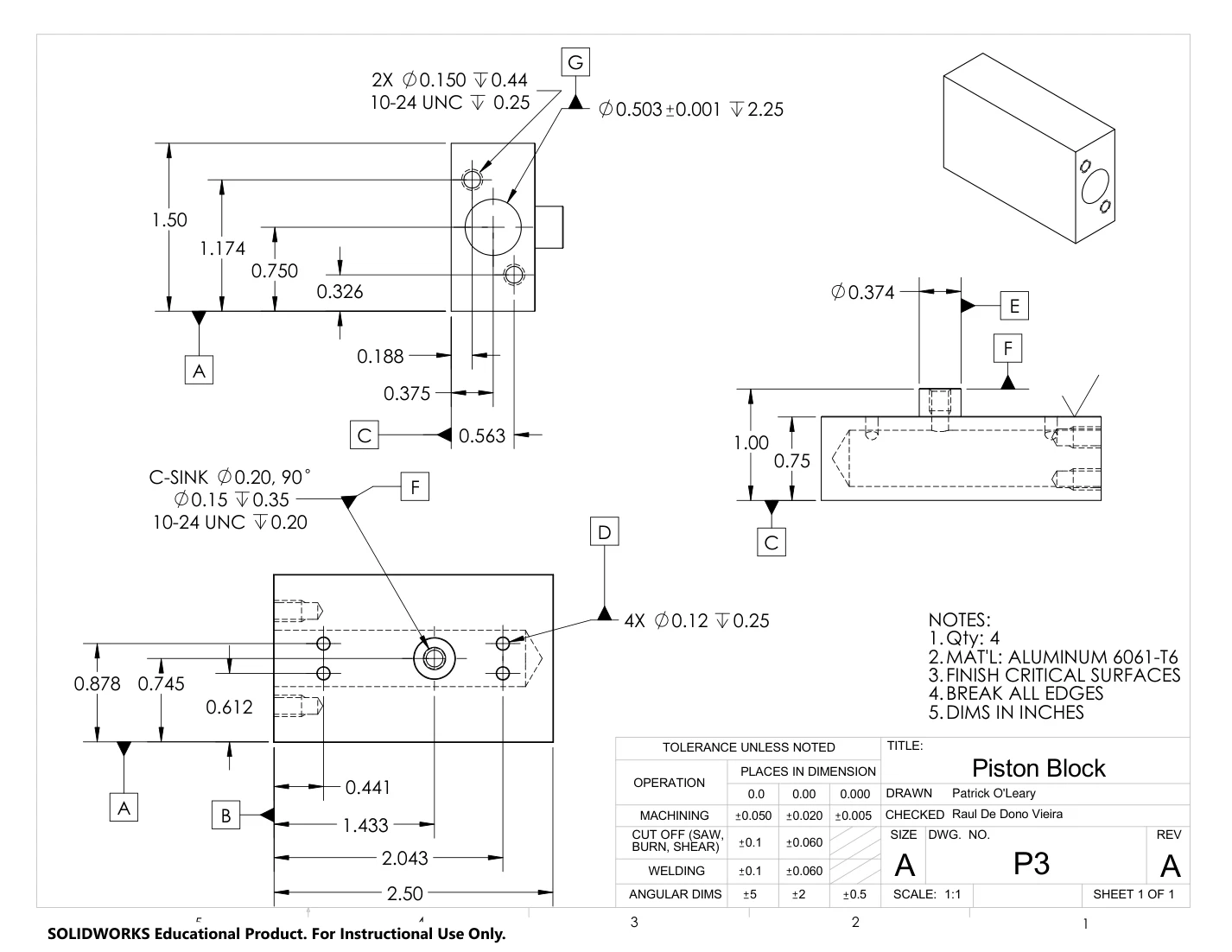
I created the piston and piston-block drawings and manufactured both components. These drawings define the dimensions, tolerances, holes, and threads needed for machining and assembly.
04 / INSPECTION & ASSEMBLY
Closing the loop with inspection.
The production package also includes inspection sheets with feature requirements, measurement methods, and dimensional bounds. These connect the drawings to the checks used during manufacturing.
My laboratory work also included designing an air-powered food slicer under cost, manufacturing, safety, and functional constraints.